Battery Door
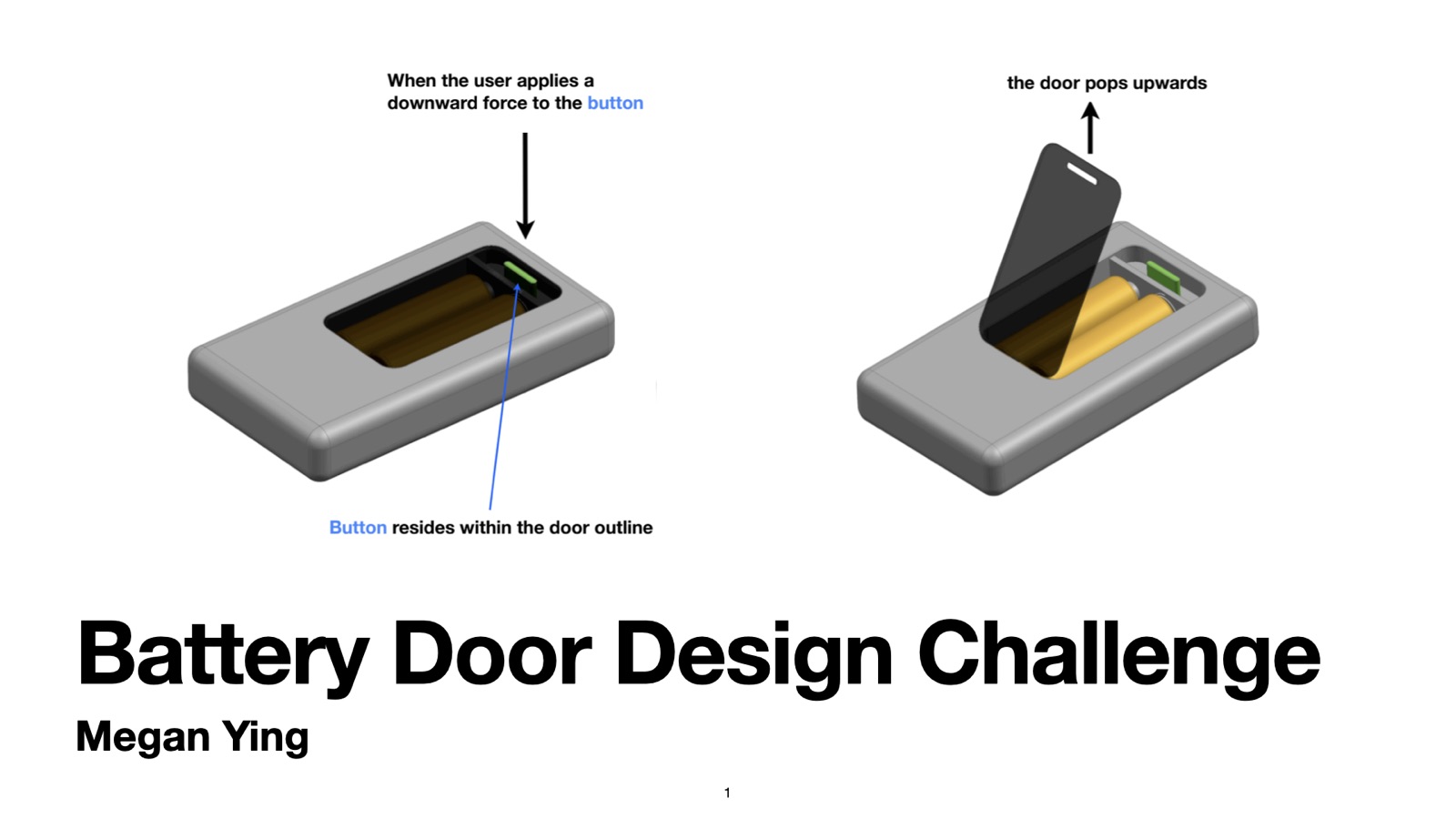
Designing a one-touch battery door mechanism that releases with a downward button press and automatically re-latches when closed.
Overview
I designed a push-button battery door for an Apple mechanical design interview challenge. A spring-loaded sliding latch converts a downward button press into horizontal release motion, allowing the door to open and automatically re-latch when closed.
I developed the assembly in Siemens NX and used hand calculations, tolerance analysis, and FEA to evaluate button travel, closing force, latch engagement, and component loading. I also planned the assembly sequence and selected materials and processes for a proposed production volume above 100,000 units per year.

Design
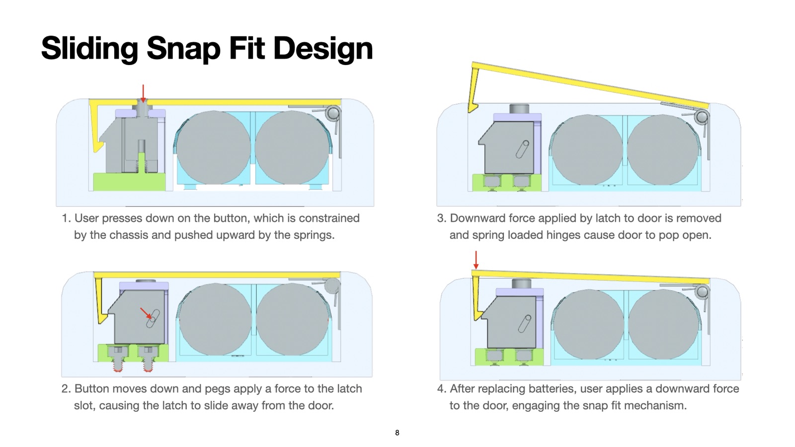
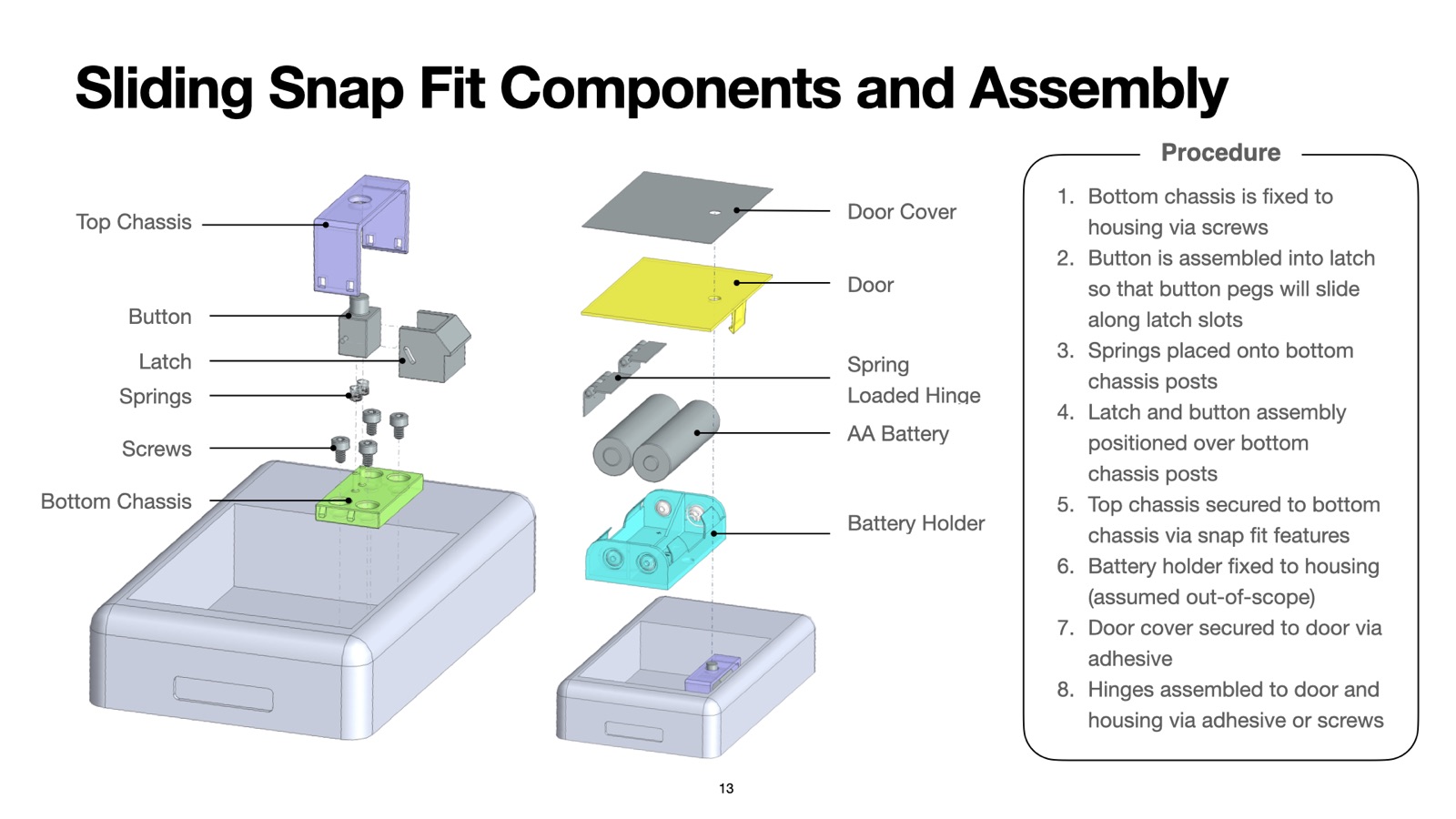
The mechanism combines a vertically guided button, a horizontal latch, return springs, and two chassis parts that locate and retain the moving components.
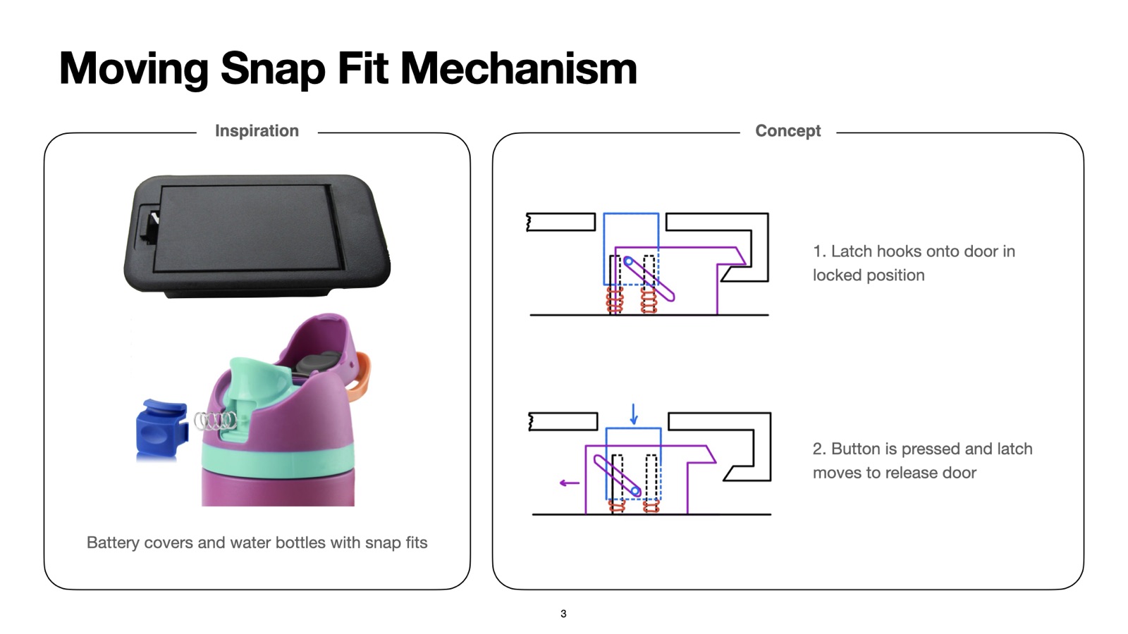
Button pegs engage angled slots in the latch. Pressing the button retracts the latch until it clears the door hook, allowing spring-loaded hinges to lift the door.
When the button is released, the springs return the button and latch. During closing, a ramp on the door hook pushes the latch aside; the latch then springs back into engagement. A flat locking surface resists release from an upward pull on the door.
I designed the top chassis to snap onto the bottom chassis, capturing the internal parts while guiding button and latch motion.

Concept Development
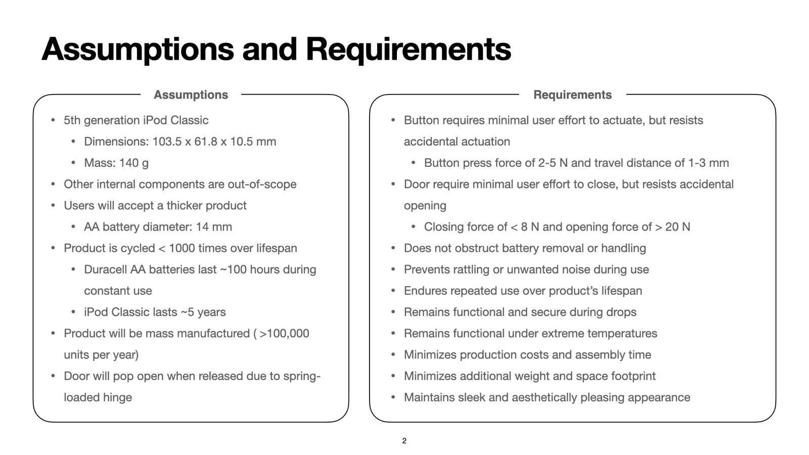
I defined requirements for button force and travel, closing force, package size, and repeated use. The key interaction targets were a 2–5 N button force, 1–3 mm travel, and a closing force below 8 N.

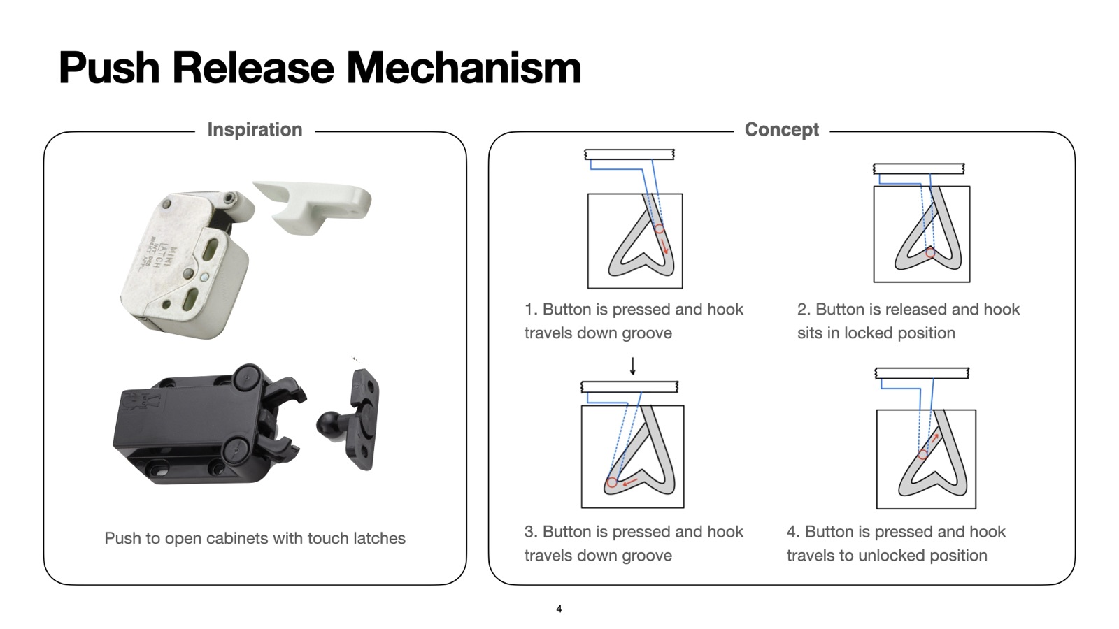
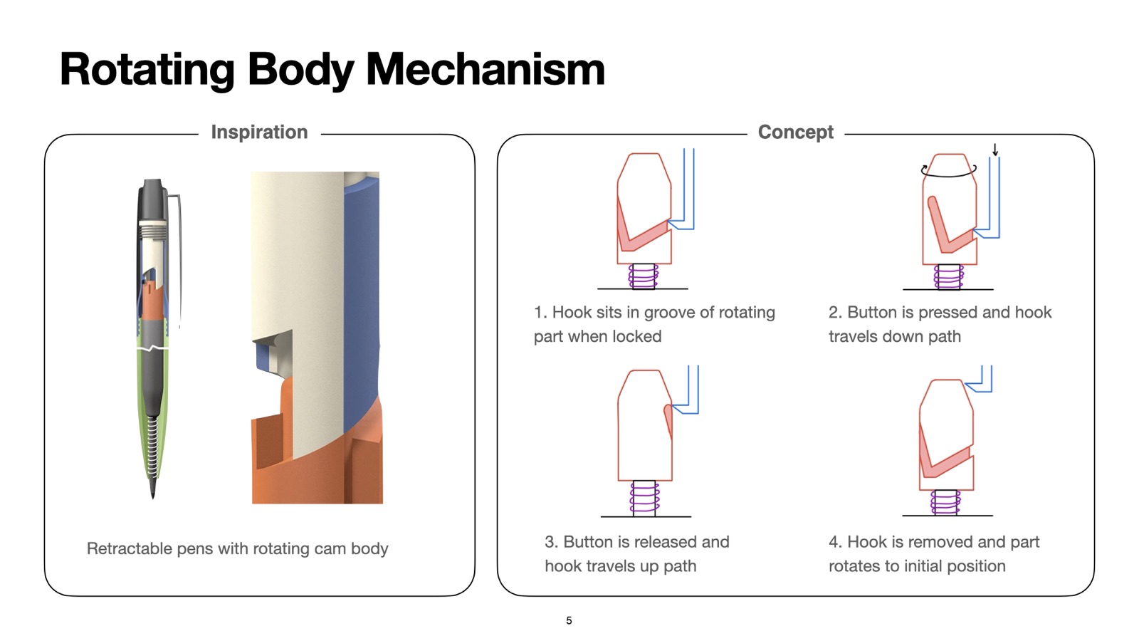
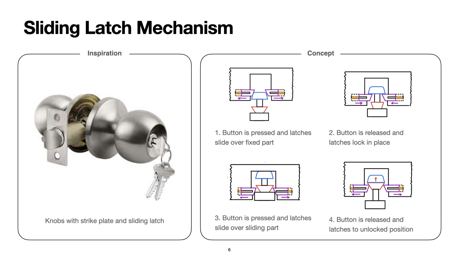
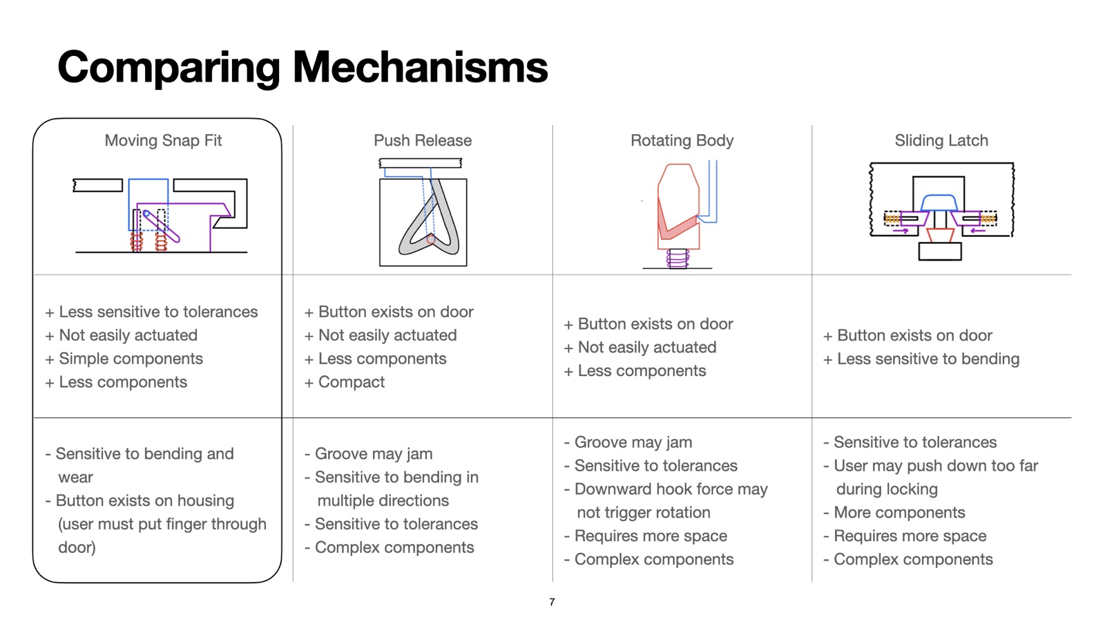
I explored four release architectures and compared their complete release and reset sequences. The tradeoffs included tolerance sensitivity, jamming, accidental actuation, component complexity, and whether the button could remain within the door perimeter.


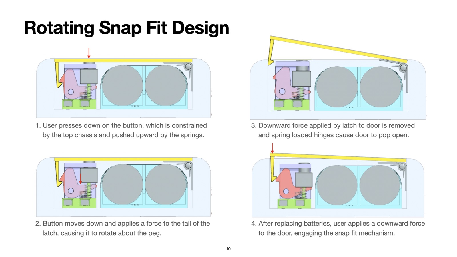
I developed sliding and rotating implementations of a moving snap fit. The sliding version uses angled slots to convert button travel into latch translation; the rotating version pivots the latch out of engagement.


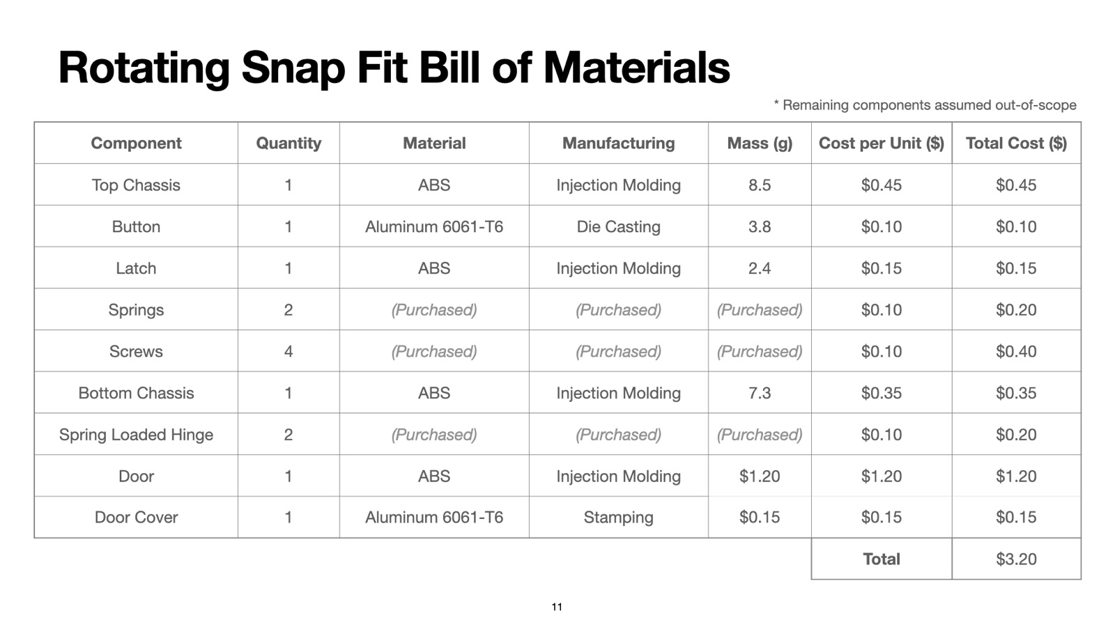
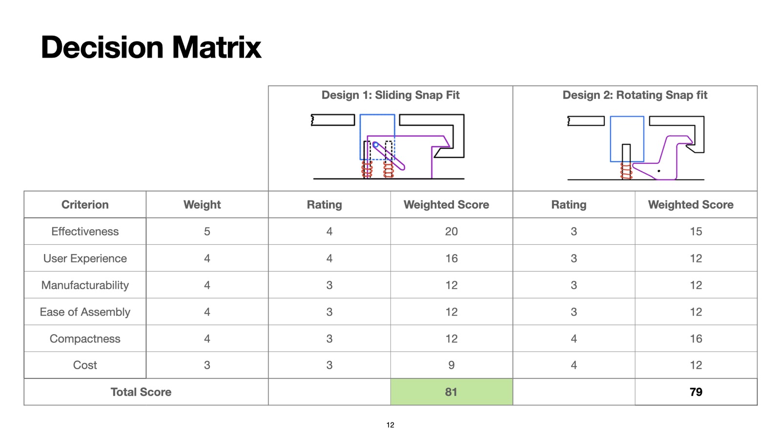
I selected the sliding version using a weighted decision matrix. It scored higher for effectiveness and user experience, which carried more weight than the rotating version’s advantages in compactness and estimated cost.
| Criterion | Weight | Sliding rating | Sliding score | Rotating rating | Rotating score |
|---|---|---|---|---|---|
| Effectiveness | 5 | 4 | 20 | 3 | 15 |
| User experience | 4 | 4 | 16 | 3 | 12 |
| Manufacturability | 4 | 3 | 12 | 3 | 12 |
| Ease of assembly | 4 | 3 | 12 | 3 | 12 |
| Compactness | 4 | 3 | 12 | 4 | 16 |
| Cost | 3 | 3 | 9 | 4 | 12 |
| Total | 81 | 79 |
Analysis & Validation
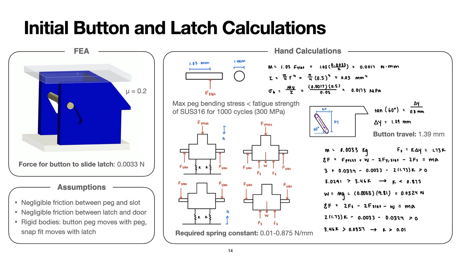
I worked backward from the latch travel needed to clear the door hook to size the angled slots, button stroke, and return springs. The calculations predicted 1.39 mm of button travel, within the 1–3 mm target.

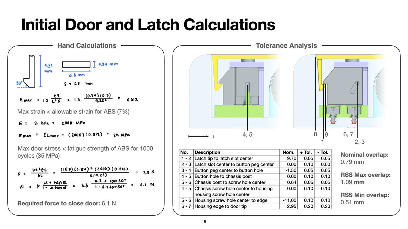
I evaluated peg bending and snap-fit stress, strain, and deflection under the modeled loads. The door calculation predicted a 6.1 N closing force, below the 8 N target. These calculations screened the geometry for the assumed service life; physical cycle testing would be needed to establish durability.

I traced the dimensional chain from the latch tip to the door hook and calculated an RSS tolerance stack-up. The predicted overlap was 0.79 mm nominal, with an RSS range of 0.51–1.09 mm. This estimate supports engagement under the modeled variation, but does not establish a worst-case tolerance bound.

I used FEA to examine peg-to-latch contact during release and door-hook deflection during closing. The simulations provided stress and deformation estimates for comparison with the hand calculations. Material assumptions in the peg analysis still need to be reconciled with the aluminum button specified in the proposed BOM.
Manufacturing & Cost
I selected proposed materials and processes based on component geometry, compliance, production volume, and user-contact surfaces.
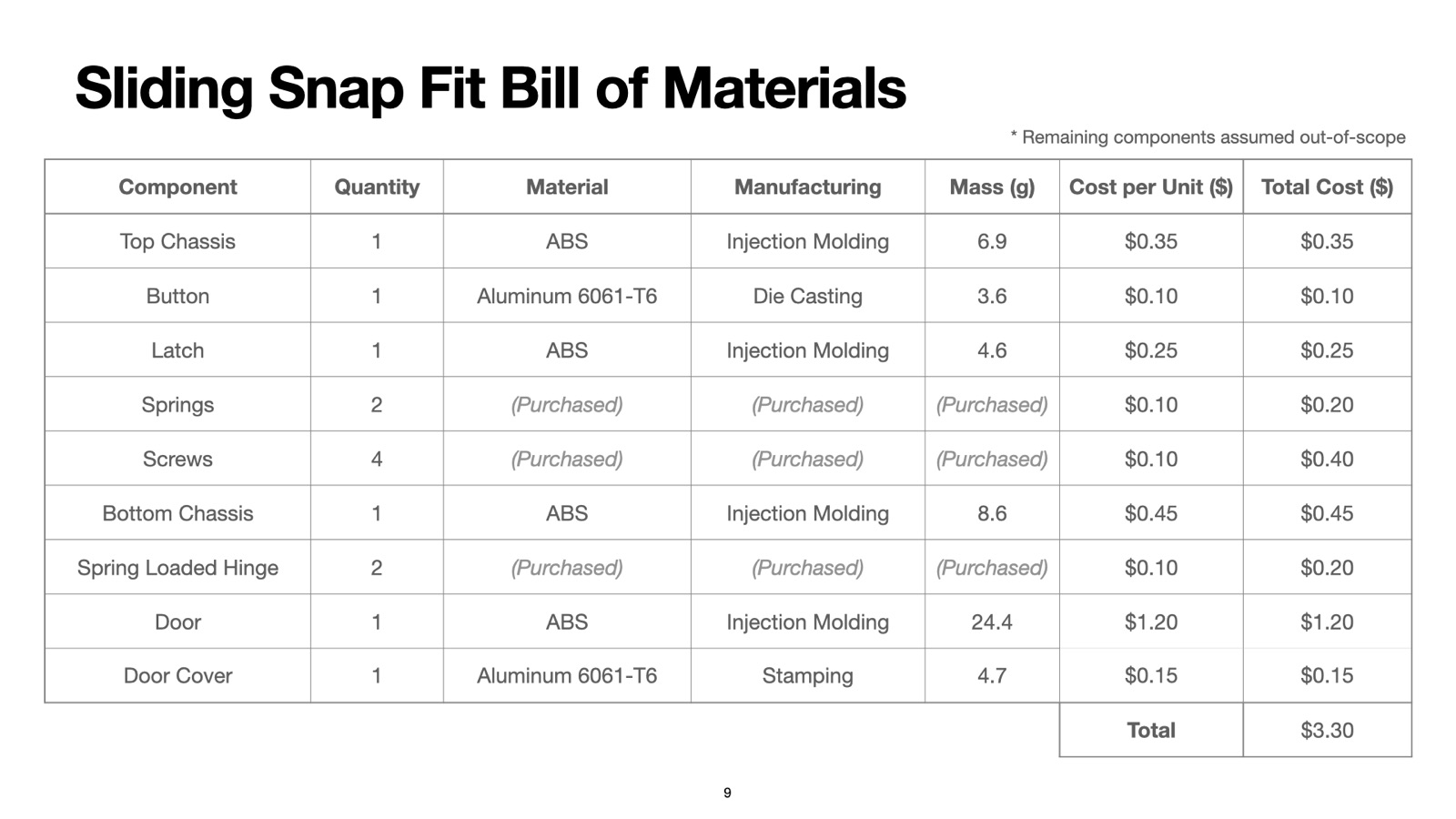
The chassis, latch, and structural door use injection-molded ABS; the button and door cover use aluminum. Springs, screws, and spring-loaded hinges are purchased hardware. The assembly sequence uses chassis snap fits to retain the release mechanism.
The estimated BOM cost was $3.30 per assembly. This is a preliminary component-cost estimate rather than a validated manufacturing quotation or complete production cost. The button alloy and forming process require further review before release.
| Component | Qty | Material | Manufacturing | Mass (g) | Unit ($) | Total ($) |
|---|---|---|---|---|---|---|
| Top chassis | 1 | ABS | Injection molding | 6.9 | 0.35 | 0.35 |
| Button | 1 | Aluminum 6061-T6 | Die casting | 3.6 | 0.10 | 0.10 |
| Latch | 1 | ABS | Injection molding | 4.6 | 0.25 | 0.25 |
| Springs | 2 | Purchased | Purchased | — | 0.10 | 0.20 |
| Screws | 4 | Purchased | Purchased | — | 0.10 | 0.40 |
| Bottom chassis | 1 | ABS | Injection molding | 8.6 | 0.45 | 0.45 |
| Spring-loaded hinge | 2 | Purchased | Purchased | — | 0.10 | 0.20 |
| Door | 1 | ABS | Injection molding | 24.4 | 1.20 | 1.20 |
| Door cover | 1 | Aluminum 6061-T6 | Stamping | 4.7 | 0.15 | 0.15 |
| Total | 3.30 |
Results
I completed the CAD assembly, release sequence, analysis, and manufacturing proposal for the sliding-latch design. Calculations predicted button travel and door-closing force within the selected targets, while the RSS stack-up predicted positive latch overlap.
The design remains an analytical concept. The next steps are to reconcile material assumptions, build a prototype, and measure actuation force, latch engagement, wear, and cycle durability.
presentation
1 / 15